Equation 1
This section contains criteria for selecting a suitable sampling site on the flue or duct and determining the representativeness of the desired location with respect to the homogeneity of the gas flow.
The probe or in-situ analyzer must be installed in a location that is accessible at all times and under any weather conditions so that repairs, routine maintenance and accuracy testing can be performed on schedule as outlined in the QA/QC manual. The degree of exposure, seasonal weather conditions, servicing and maintenance, susceptibility to lightning strikes, and vibration of the duct or platform are some of the considerations when choosing a location for a probe or in situ analyzer.
The flow pattern at the sampling site must be determined prior to the installation of the flow sensor. The presence of a cyclonic flow pattern will add considerable complexity to both certification and operation of the installed sensor.
The probe or in situ analyzer must be installed in a location where the flue gases are well mixed. The degree of turbulence and mixing time are major factors that influence the extent of stratification of the flue gases.
The extent of CO2 (or O2) stratification of the flue gases at any location must be determined using the applicable test methods. The procedures outlined in Section 4.2.1 must be carried out at a proposed analyzer installation site to determine the extent of stratification before installing the CEM system. If significant gas stratification of any of the measured species is present at the proposed location, then an alternative sampling location must be selected where the flow is non-stratified.
Before the installation of the flow monitor, a number of velocity traverses must be carried out at the proposed sensor installation location over a range of loads using the equipment and procedures found in Method B of Reference Method EPS 1/RM/8 (Reference Methods for Source Testing: Measurement of Releases of Particulate from Stationary Sources, Environment Canada, December 1993, as amended). The degree of cyclonic flow is determined using the procedures found in Method A of Reference Method EPS 1/RM/8. These measurements will provide a basis for the location of the sensor and will also demonstrate the absence of cyclonic flow (average rotational angle ≤15 degrees). The location of sampling ports must be selected so as to avoid interference between the flow monitor, the concentration measurement point(s) or path, and other sampling probes.
If a single-point stack gas velocity sensor is being installed, the sensing tip must be located at a point yielding velocity measurements within the specifications over the full range of loads. The velocity profile data must be used to select the optimum measurement point.
A minimum of nine sampling points must be used in the stack or duct, applying the procedures for selecting sampling points found in Reference Method EPS 1/RM/8. Using two automated systems with similar response characteristics, the concentration of a target gas must be measured at each of the sampling points in the matrix with one system (traversing system), while simultaneously measuring the target gas concentration at a fixed or reference location, usually at the centre of the flue or duct.
Note that a stratification test must be carried out data for each gaseous species measured by the installed CEM system (either CO2 or O2).
The concentration of the gas measured at the fixed location (stability reference measurement) in the flue or duct serves as an indicator of the stability of the gas flow. If this concentration varies by more than ±10% of the average concentration for longer than one minute during this test, the stratification test must be carried out when more stable conditions prevail.
Note that the installed analyzer in the CEM system, which withdraws a sample from a fixed point, is acceptable as the stability reference measurement for the stratification test. The response characteristics of the reference and the traversing analyzers must be similar.
The concentration of a target gas must be measured at each of the sampling points in the matrix. At the conclusion of the traverses, the measurement of the concentration must be repeated at the initial measurement point. If the concentrations differ by more than ±10% for the pre- and post-test values at this point, stratification must be retested when more stable conditions prevail.
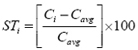
The degree of stratification for each species is calculated at each traverse point within the gas flow using Equation 1.
where:
STi = stratification in %
Ci = concentration of the measured species at point i
Cavg = average of all measured concentrations
The flow in the stack or duct is considered to be stratified if any calculated value using Equation 1 exceeds 10%.