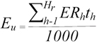
The annual CO2 mass emissions, in tonnes, using a CEM system must be calculated from hourly average CO2 mass emission rates using Equation 24.
Equation 24
where:
Eu = quantity of CO2 emissions from the EGU, “u”, during the calendar year from combustion of fuel, in tonnes
ERh = hourly CO2 mass emission rate during EGU operation, in kg/hour
Th = EGU operating time, in hours or fraction of an hour
HR = number of hourly CO2 mass emission rates available during the calendar year
Hourly average CO2 mass emission rates, in kg/hour, must be determined according to one of the following options:
Option A: wet carbon dioxide-based measurement systems where both the stack gas flow rate and CO2 concentration are measured on a wet basis in accordance with Section 7.2.
Option B: dry carbon dioxide-based measurement systems where the stack gas flow rate is measured on a wet basis and the CO2 concentration is measured on a dry basis in accordance with Section 7.3.
Option C: wet oxygen-based measurement systems where both the stack gas flow rate and O2 concentration are measured on a wet basis in accordance with Section 7.4.
Option D: dry oxygen-based measurement system where the stack gas flow rate is measured on a wet basis and the O2 concentration is measured on a dry basis in accordance with Section 7.5.
This option is applicable in all situations.
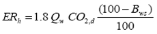
When both the CO2 concentration and stack gas flow rate are measured on a wet basis, the hourly average CO2 mass emission rate must be calculated using Equation 25.
Equation 25
where:
ERh = hourly average mass emission rate of CO2 during EGU operation in kg/h
1.8 = CO2 gas density in kg/Sm3
Qw = hourly average stack gas volumetric flow rate during EGU operation in WSm3/h on a wet basis
CO2,w = hourly average stack gas concentration of CO2 during EGU operation, in % of volume and on a wet basis
This option is applicable when either:
When the CO2 concentration is measured on a dry basis whereas the stack gas flow rate is measured on a wet basis, the hourly CO2 mass emission rate must be calculated using Equation 26.
Equation 26
where:
ERh = hourly average mass emission rate of CO2 during EGU operation in kg/h
1.8 = CO2 gas density in kg/Sm3
Qw = hourly average stack gas volumetric flow rate during EGU operation in WSm3/h on a wet basis
CO2,d = hourly average stack gas concentration of CO2 during EGU operation, in % of volume and on a dry basis
Bws = hourly average stack gas moisture content determined in accordance with Section 7.6 during EGU operation, in % of volume
This option is only applicable when either:
The stack gas CO2 wet concentration can be derived from measuring the stack gas O2 wet concentration using the following methods:
If neither of these conditions can be met, a carbon dioxide-based measurement system must be used.
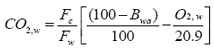
When measuring both the stack gas flow rate and O2 concentration on a wet basis and no water other than that generated during the combustion process is introduced into the gas flow, then the hourly average stack gas CO2 wet concentration must be calculated using Equation 27.
Equation 27
where:
CO2,w = hourly average stack gas concentration of CO2 during EGU operation, in % and on wet basis
Fc = ratio of the volume of CO2 resulting from the combustion of fuel with air, to the amount of heat produced in DSm3/GJ
Fw = ratio of the volume of wet gas resulting from stoichiometric combustion of the fired fuel with air to the amount of heat produced in Sm3/GJ
Bwa = hourly ambient air moisture content determined in accordance with Section 7.7 during EGU operation, in % of volume
O2,w = hourly average stack gas concentration of O2 during EGU operation, in % of volume and on a wet basis
The CO2 wet concentration calculated by Equation 27 is then introduced in Equation 25 to determine the mass emissions of CO2. For any hour where Equation 27 results in a negative hourly average CO2,w value, a value 0.0% shall be recorded.
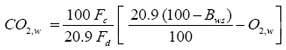
When measuring both the stack gas flow rate and O2 concentration on a wet basis and the CEM system is installed after a pollution control device that reduces the flue gas temperature so that the exit gas is saturated or contains liquid water then the hourly average CO2 wet concentration must be calculated using Equation 28.
Equation 28
where:
CO2,w = hourly average stack gas concentration of CO2 during EGU operation, in % and on a wet basis
Fc = ratio of the volume of CO2 resulting from the combustion of fuel with air, to the amount of heat produced in DSm3/GJ
Fd = ratio of the volume of dry gas resulting from stoichiometric combustion of the fuel with air to the amount of heat produced in WSm3/GJ
Bws = hourly average stack gas moisture content determined in accordance with Section 7.6.2 during EGU operation, in % of volume
O2,w = hourly average stack gas concentration of O2 during EGU operation, in % of volume and on a wet basis
The hourly average CO2 wet concentration calculated by Equation 28 is then introduced in Equation 25 to determine the mass emission of CO2. For any hour where Equation 28 results in a negative hourly average CO2,w value, a value 0.0% shall be recorded.
This option is only applicable when no water other than that generated during the combustion process is introduced into the gas flow.
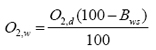
When measuring the stack gas flow rate on a wet basis and the O2 concentration on a dry basis and no water other than that generated during the combustion process is introduced into the gas flow, the hourly average stack gas O2 wet concentration must be derived from the hourly average stack gas O2 dry concentration using Equation 29.
Equation 29
where:
O2,w = hourly average stack gas concentration of O2 during EGU operation, in % of volume and on a wet basis
O2,d = hourly average stack gas concentration of O2 during EGU operation, in % of volume and on a dry basis
Bws = hourly average stack gas moisture content determined in accordance with Section 7.6 during EGU operation, in % of volume
The hourly average stack gas O2 wet concentration must then be inserted into Equation 27 to determine the hourly average stack gas CO2 wet concentration which must then inserted into Equation 25 to determine the hourly average CO2 mass emission rate.
When applying equations 26, 28 and 29, the hourly average stack gas moisture content must be determined using one of the methods described in sections 7.6.1 to 7.6.3.
Section 7.6.1 applies to stack gas moisture monitoring systems that use a wet O2 monitor that meets the specifications set out in Table 3 and Table 5 of this document where no water other than that generated during the combustion process is introduced into the gas flow.
Section 7.6.2 applies where the CEM system is installed after a pollution control device that reduces the flue gas temperature so that the exit gas is saturated or contains liquid water.
Section 7.6.3 applies where an alternative moisture monitoring system is used.
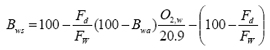
Where a wet O2 monitor that meets the specifications set out in Table 3 and Table 5 of this document is used for determining the stack gas moisture content and no water other than that generated during the combustion process is introduced into the gas flow, then the stack gas moisture must be determined using Equation 30.
Equation 30
where:
Bws = hourly average stack gas moisture content during EGU operation, in % of volume
Fd = ratio of the volume of dry gas resulting from stoichiometric combustion of the fuel with air to the amount of heat produced in DSm3/GJ
Fw = ratio of the volume of wet gas resulting from stoichiometric combustion of the fuel with air to the amount of heat produced in WSm3/GJ
Bwa = hourly ambient air moisture content during EGU operation, in % of volume
O2,w = hourly average stack gas concentration of O2 during EGU operation, in % of volume and on a wet basis
When the CEM system is installed after a pollution control device that reduces the flue gas temperature so that the exit gas is saturated or contains liquid water then the stack gas moisture content must be determined from the stack gas temperature by applying equations 31 and 32.
Equation 31
where:
Bws = hourly average stack gas moisture content during EGU operation, in % of volume
pH2O = hourly partial water vapour pressure of the stack gases in mm Hg, as calculated with Equation 32
Pstack = hourly stack gas absolute pressure during EGU operation in mm Hg
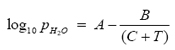
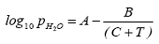
Equation 32
where:
pH2O = hourly partial water vapour pressure of the stack gases in mm Hg
A = constant = 8.0886767
B = constant = 1739.351
C = constant = 234.1
T = hourly stack gas temperature during EGU operation in °C
Note: the constants A to C apply to a 55 to 80°C temperature range.
Alternative stack gas moisture monitoring systems may be used for determining the hourly average stack gas moisture content, if it is demonstrated that the system is able to calculate the factor (100 - Bws) with an error ≤ 2.0%, hourly all year round.
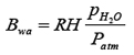
When applying equations 27 and 29, the hourly ambient air moisture must be determined using equations 33 and 34:
Equation 33
where:
Bwa = hourly ambient air moisture during EGU operation in % of volume
RH = hourly relative humidity, in %, during EGU operation, as measured with traceable thin film capacitance sensor, or equivalent
pH2O = hourly partial water vapour pressure at ambient air temperature in mm Hg, as calculated with Equation 34
Patm = hourly atmospheric pressure during EGU operation, mm Hg, calculated as 760 mm Hg minus
8.33 mm Hg per 100 m elevation above sea level
Equation 34
where:
pH2O = hourly partial water vapour pressure at ambient air temperature in mm Hg
A = constant = 8.184254
B = constant = 1791.3
C = constant = 238.1
T = hourly ambient air temperature in °C
Note: the constants A to C apply to a 0 to 30°C temperature range.